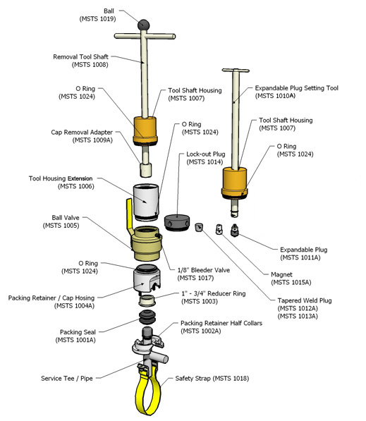


Remove 3/4" Pipe Type Service Tee
With the Mazco Safe-T-Stopper®
Usage instructions for service tee connections
- 3/4", 1", 1 1/4", 1 1/2" & 2" pipe diameter
Preparation and Pre-Fitting
|
1. Prepare service tee by removing all protective wrapping from the upright and lateral branch portions of the service tee. Clean surface to bare metal finish between threaded cap and lateral branch. 2. Before mounting Safe-T-Stopper®, insure the cap removal fits properly over the service tee cap (fig. 1). The tool should bottom out on the cap with good magnetic attachment strength. Some hand filing or grinding may be necessary to remove manufacturer's stamping or casting ridges. Grind the lower casting flange on the cap to reduce the chances of cap binding in the housing. Many caps are not completely round and may cause cap binding once inside the cap housing. |
|
Mounting the Safe-T-Stopper ®
|
|
1. Take a firm two-handed grip on one packing seal at a time and stretch over the service tee cap. The first packing seal must be installed with the bevel facing downward (Fig. 2). The second packing seal must be installed with the bevel facing upward. When both packing seals are over the cap, pull both seals up under the cap (Fig. 3). NOTE: 3/4" and 1-1/2" require only one seal with the use of the reducer ring. |
|
2. Using a pipe wrench, loosen the service tee cap until cap is hand-tight. NOTE: Do not loosen too much as the cap could disengage from threads. The cap removal tool is not designed to break the cap loose. 3. Place the two packing retainer half-collars under the packing seals with the beveled edges upward and the collar cutaway over the service tee branch (Fig. 3). |
|
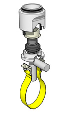 Fig. 4 |
4. Place the packing retainer and cap housing (with or without valve) over the packing retainers, aligning the two packing retainer bolts through the packing retainer half-collars (Fig. 4). Note: The ¾" and 1 ½" service tee requires a reducer ring between the single seal and packing retainer/cap housing. Place the reducer ring inside the housing with the o-ring mounted upward. 5. Place safety restraining strap assembly over one packing retaining bolt and install packing retainer nut hand-tight. Loop restraining strap under main line and connect other end of restraining strap assembly to the second packing retainer bolt. Place packing retainer nut on bolt and hand-tighten (Fig. 4). Note: Tools with side buckles must have the safety strap secured to the buckles and tightened. 6. Using a 9/16" wrench, slowly tighten packing retainer nuts evenly while ensuring the packing retainers are moving upwards into retainer housing. Be sure to keep entire tool raised up under service tee cap. Tighten packing retainer nuts until the tool is secure on the service tee. Do not over-tighten. |
| 7. Check to ensure the service tee cap is centered inside the retainer and cap housing. The tool should be straight upward when mounted correctly on the service tee. 8. Thread ball valve onto retainer and cap housing if not already secured. Ball valve handle should be in upward position and bleeder valve on upper side of ball valve. Hand-tight is sufficient"”do not use wrenches. Valve can be left in open position (Fig. 5). |
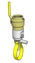 Fig. 5 |
Removing Threaded Cap
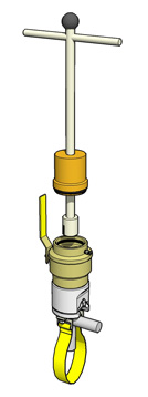 Fig. 6 |
CAUTION: If at any point during these procedures there is any apparent release of gas or other product stop the procedure immediately, and take corrective action. 1. Thread cap removal tool onto ball valve (Fig. 6). Hand-tight is sufficient. Do not use wrenches. NOTE: Apply a light film of grease to the tool shaft to assist in shaft movement. 2. Close 1/8" bleeder valve on the upper side of the ball valve. 3. Lower cap removal tool onto cap and engage the slotted tool with the two raised castings of the cap. 4. Rotate tool counter-clockwise to remove the cap. Be sure to press down firmly while turning to ensure the tool does not hydraulic away from the cap. A slight ratchet effect will be felt and heard once the cap threads are disengaged from the service tee threads. |
|
5. Slowly raise the cap removal tool until completely up and out of the valve (Fig. 7). NOTE: Once cap has been removed, DO NOT leave tool unattended. Place the lock-out plug on to tool if unattended. Follow company lock-out procedures |
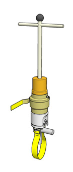 Fig. 7 |
Inserting the Expandable Plug
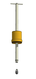 Fig. 8 |
1. Place the expandable plug onto the expandable plug tool shaft in the tighten position. (Right side while looking down tool shaft.) Be sure the expandable plug is completely relaxed to ensure a loose fit inside of service tee (Fig. 8). 2. Before mounting expandable plug setting tool into valve, place tool along side of valve to get a distance measurement from the bottom of the expandable plug to the top of the expandable plug tool housing. Slide marking indicator down shaft to top of tool housing. This will ensure the expandable plug is located just above the main line and far enough below the service tee branch. NOTE: Be sure to fully retract the expandable plug inside the plug setting tool housing before mounting the tool onto the valve. 3. Thread expandable plug setting tool onto the top of the ball valve (Fig. 9). Hand-tighten is sufficient. Do not use wrenches. NOTE: Apply a light film of grease to the tool shaft and spring loaded inner drive shaft at the top of expandable plug setting tool to assist in shaft movement. |
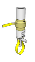 Fig.9 |
4. Close 1/8" bleeder valve on ball valve.
5. Open ball valve.
6. Slowly lower expandable plug down into service tee until the plug contacts the main or the pre-measured depth indicator in step 2 of the 'Inserting the Expandable Plug' Section.
7. Turn expandable plug tool handle clockwise while holding the tool shaft, until tight. Allow expander plug to set for two to three minutes, then retighten to ensure plug is set tight.
8. Press expandable plug tool shaft down slightly while turning tool shaft clockwise approximately ¼" to disengage from expandable plug.
9. Raise expandable plug setting tool shaft completely upward.
10. Open service line riser valve and vent service line to a safe location.
11. Once pressure is released, open small bleeder valve on ball valve to confirm all pressure has been released from tool.
|
NOTE: If cap or expandable plug were ever to become disengaged from tool, attach magnet retrieval tool to the expandable plug setting tool to retrieve disengaged item (Figure 10). |
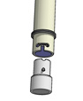 Fig. 10 |
12. Remove Safe-T-Stopper® tool if the service tee is to be removed. Do not remove Safe-T-Stopper® tool if service tee is to be put back in service.
To Remove Service Tee
Note - Companies that wish to remove the service tee by cutting off below the branch must ensure the expander plug is set sufficiently to remain in the service branch, and follow their own written procedures for tee removals. Higher pressures and contaminants on the pipe wall could affect the integrity of the expander plug retention.
|
1. Measure distance from top of service tee to the top of the expandable plug. 2. Mark service tee cut-off location approximately 5 mm above the top of the threaded screw in the center of the expandable plug. 3. Using a pipe cutter, or other tools approved by your company standards, cut off service tee. 4. Place properly-sized tapered plug into the service tee stub above the expandable plug (Fig. 11). Be sure of correct fit due to different service tee wall thicknesses (Sch 40, Sch 80, etc.) . 5. Once correct tapered plug is set in place, tap the plug in place with a hammer and back-weld entire plug circumference onto service tee stub. |
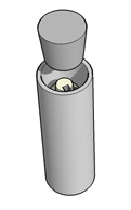 Fig. 11 |
To Put Service Tee Back Into Service or Capping Branch Only.
The service tee can be put back into service by reversing procedures.